The present tutorial is a step-by-step guide using the
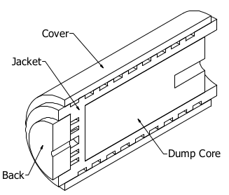
Geometry Editor to build a complex geometry of the following CERN beam dump
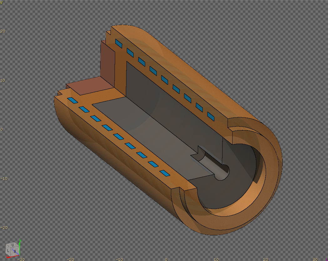
Final geometry in flair, cut with a rectangular clip body to see the interior
To follow this tutorial, you will need:
Basic knowledge of FLUKA, especially the use of combinatorial geometry
First thing you have to do is to collect all technical drawings, photos information
concerning your geometry to build.
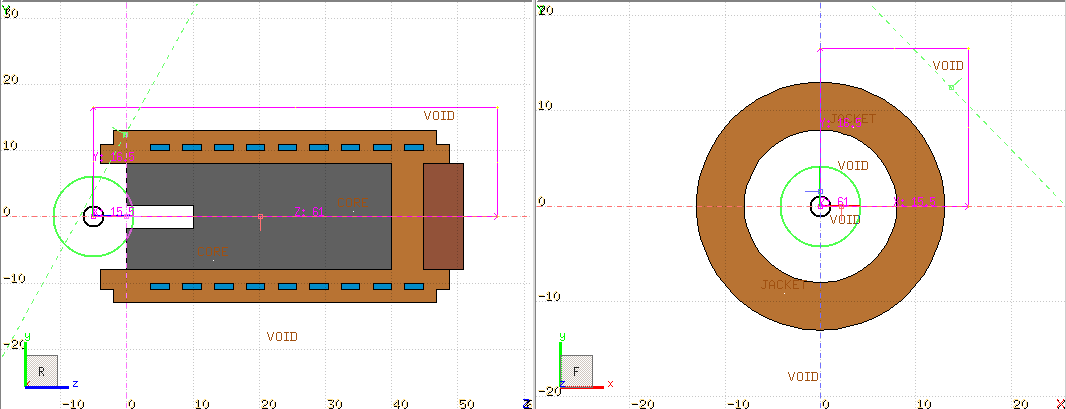
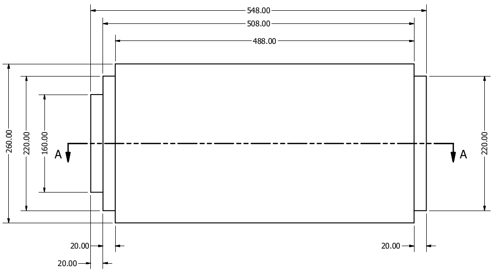
3D representation of the dump cut in half External dump dimensions AA cross section
Please pay attention to:
The cylindrical symmetry
All dimensions in mm, while FLUKA is using cm
The beam is entering the dump from the right side through the 10cm long hole
in order to minimize the back scatterings.
The cooling water is entering from the center hole on the left side and it
follows a spiral path around our dump. Since FLUKA do not have any spiral
shaped body we need to approximated it with cylinders.
Launch $ flair by typing the command,
or from the system application menu
Flair
Select the
Flair
tab
(if it is not already selected)
Click on the label
New ▼
(not on the icon) of the button
New ▼
To open a drop downlist with the available templates.
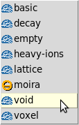
Select the
void
template.
The void template.
The void template will generate a basic FLUKA input with two
concentric spherical regions named BLKBODY
and VOID
Fill in the Title: field something like: LINAC4 main dump
Click Yes on the popup-dialog asking you to update the TITLE card
Optionally you can add also a small note describing the present project
Finally click on the save icon on the left of the tab bar.
Save it as maindump.flair preferably save it under a new directory.
Please use this name to be consistent in all the following commands.
You can create directories directly in the save dialog there is a dedicated
button for it.
Control-S key is a shortcut for save
as an image layer in the Geometry Editor to draw the geometry on top of it.
Download main_dump.png technical
drawing showing the AA cross section of the dump.png,
and save it in the same directory with our project.
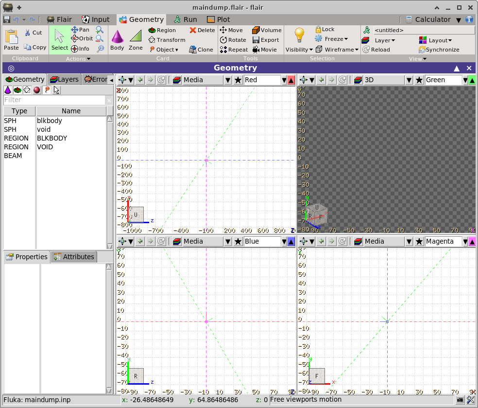
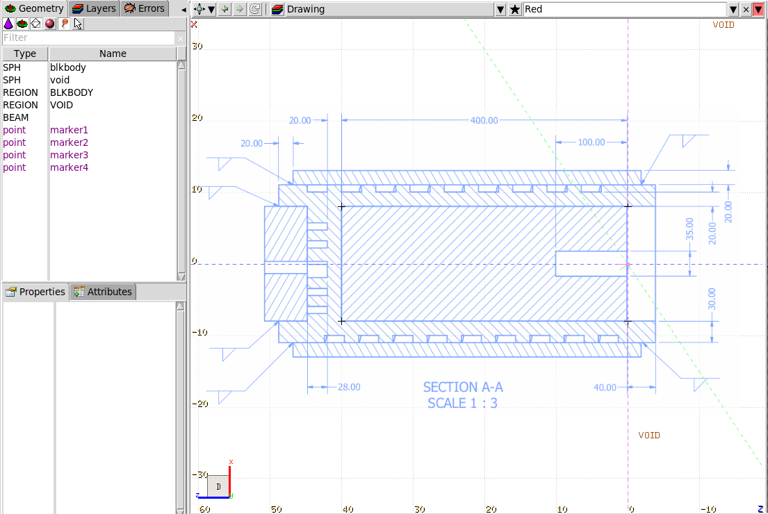
Click on the
Geometry
tab to visualize the geometry
The 4 viewports, clockwise from the top-left:
Top/Up: Red (Z:X)
3D: Green
Front: magenta (X:Y)
Right: blue (Z:Y)
The first thing to do is to choose the geometry coordinates. For this
tutorial, the following coordinate system will be used:
Z: direction of the beam, horizontal
X: horizontal axis perpendicular to the beam
Y: vertical axis pointing upward
Using the Middle mouse button and a combination of Shift,
Control keys you can navigate very quickly in the geometry.
Panning press and hold the Middle mouse button in any
viewport and drag the mouse.
Set pivot point click once the Middle mouse button the
viewport will center to this location and set it as a pivot point for
the rotations
Orbit press Control and the Middle mouse button
the viewport will rotate. Useful only when displaying in 3D. It should
be used with Setting the pivot point
Zoom In/Out rotate the Wheel of your mouse
Pan Backward/Forward press Control and rotate the mouse
Wheel
Orientation Cube hover the Mouse over the orientation cube
on the bottom-left corner of each viewport. The cube will become bigger
and interactive. Click at any location, or the colored axis to change
the orientation of the viewport and or align the axis
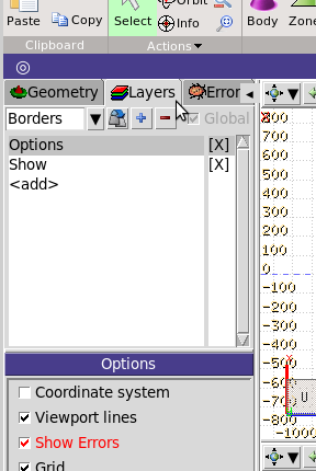
Click on the
Layers
tab on the left listbox.
It will change to the layers definition
There are 4 predefined layers
Borders - 2D display with only the boundaries of regions
Media - 2D display with the regions colored with their
material
3D - 3D basic display
Lattice - like the Media with the lattice
viewing and voxel enabled
Click the to create a new layer,
automatically named Layer 01
Click on the name and change it to Drawing
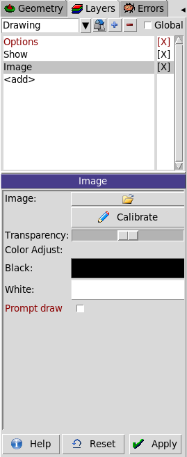
Click on the <add> last-entry in the layer listbox
Select the Image from the drop down list.
Click on the button to load
the drawing.
The image shows the top cross section of the geometry therefore the image
coordinates correspond to horizontal-Z, vertical-Y, according
to the previous definition of our coordinate system. Since the beam is
entering from the right-to-left the horizontal-Z is reversed
moving to positive values from right-to-left.
Any bitmap image can be imported (jpg, gif, png, bmp, ... directly
converted from the technical image or even from paper scanning!)
Click the button
Calibrate
below the image one,
to open the image calibration window
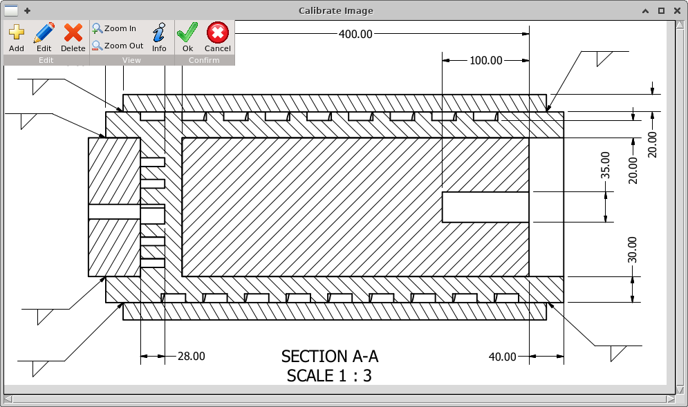
In this window, the user has to provide minimum 4 points in order the
program to be able calculate the conversion from the image coordinates to the
geometry. 4 points is the minimum to calculate the position, orientation, aspect
and the skewness of the image. The more points you provide the more accurate the
calibration will be done.
In case you provide only 3 points it will assume that the plot is perfectly
orthogonal, no skewness and with an aspect ratio of 1
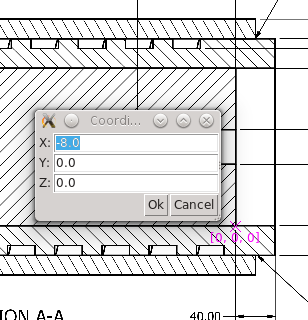
Click the
Add
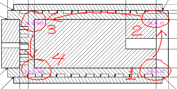
button. The mouse cursor will convert to a cross.
Add the first point/marker at almost bottom-right of the image as shown
Enter the coordinates for the [1] first marker: [X: -8.0, Y: 0.0, Z: 0.0].
The drawing shows a diameter of the Dump Core as 160mm.
Initially the points are not needed to be accurately placed, we will correct
them later.
You can Double Click on a marker to pop-up again the window with the
coordinates to correct if needed.
Add 3 more markers as shown in the drawing
Markers coordinates:
#
X
Y
Z
1
-8
0
0
2
8
0
0
3
8
0
40
4
-8
0
40
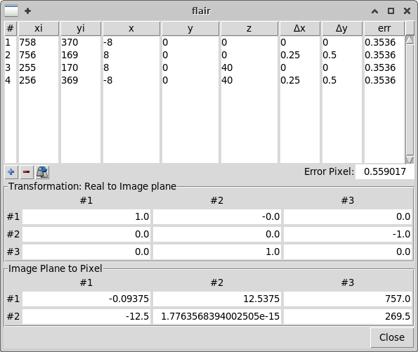
Click the
Info
it will open a window with all the markers pixel position xi,yi
3D coordinates x,y,z error and transformation matrix to be used.
The fields xi,yi,x,y,z are editable in this window so you
can fine tune if you want also here the parameters
Close the Information window
If the error is too big you can correct the calibration.
by zooming in with the Mouse-wheel.
Pan close to the markers and with the Middle mouse button
or with the keyboard Arrows.
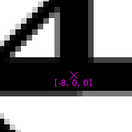
Drag the marker using the left mouse button and place it to the
center of the line intersection as accurate as possible
Repeat the procedure for all markers
Click again on the
Info
dialog and see how the Pixel error is decreasing (or increasing).
In this specific case our image is from a image processing program (not scanned
from paper), so the exact position of the markers should lie in the center of
the pixels, with decimal .5 The pixels are perfectly aligned horizontal and
vertical so convert all decimals values to .5.
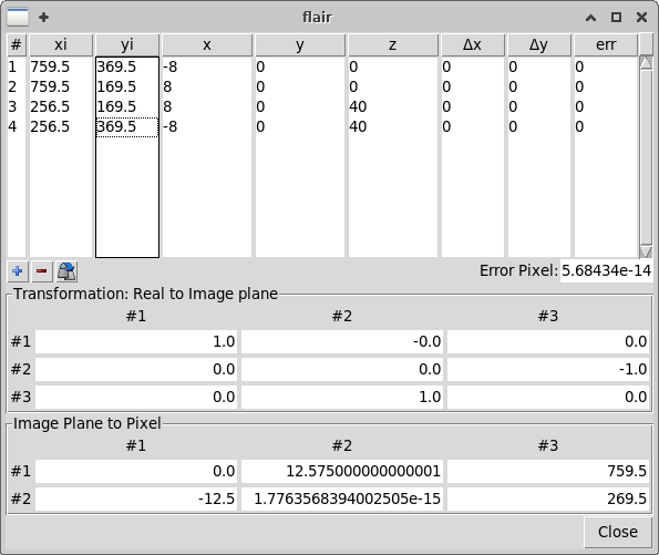
Markers 1,2 and 3,4 have the same xi,
while 1,4 and 2,3 have the same yi, reducing the error to
zero!
To edit the table move the cursor/mouse to the pixel value
xi,yi and click Enter.
The error should be almost zero
Click
Ok
to close the calibration window
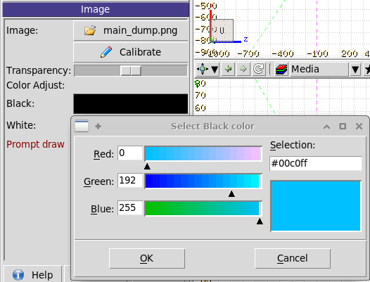
Click on the Black: color button to remap the image "black"
to some other color e.g. cyan.
This is done since the image lines are black, and it will be confused with the bodies
boundaries which are also black.
Check the Prompt draw option
Normally the background image is displayed when the viewport is idle. However,
during the editing process the background image is convenient to be visible all
times.
The red text color of the option indicates a
time consuming process, which when active delays the screen refreshing.
Click on the
Apply
button
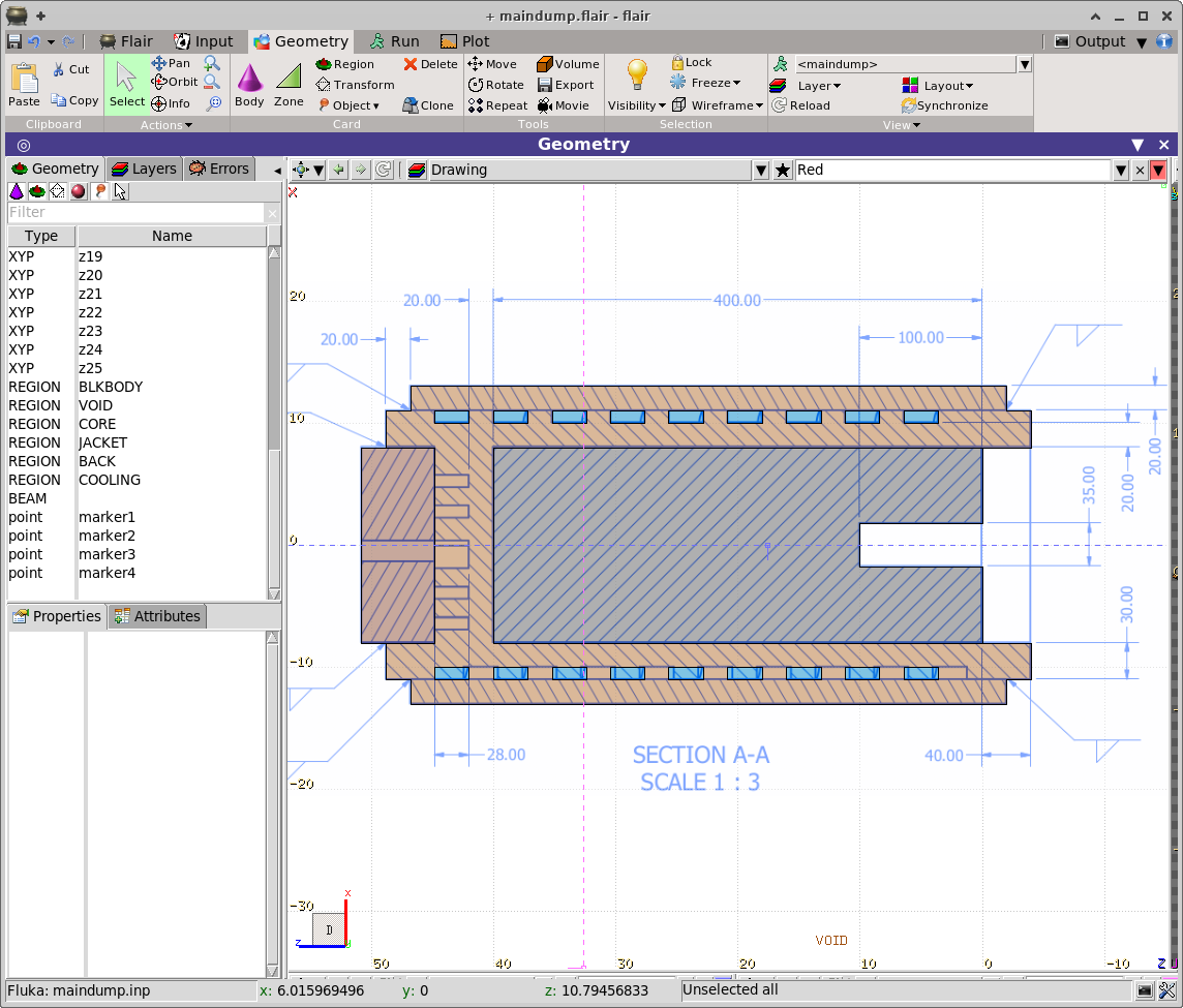
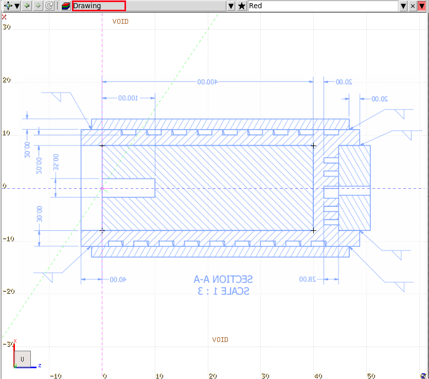
Maximize the Red (Z:X) viewport.
Select the Drawing layer from the drop-down list of the viewport
Note that the image is reflected due to the coordinate system we used.
Benefiting from the cylindrical symmetry of the geometry, only one viewport
is needed, however the user should be careful while editing the geometry on
the impact on the other viewports.
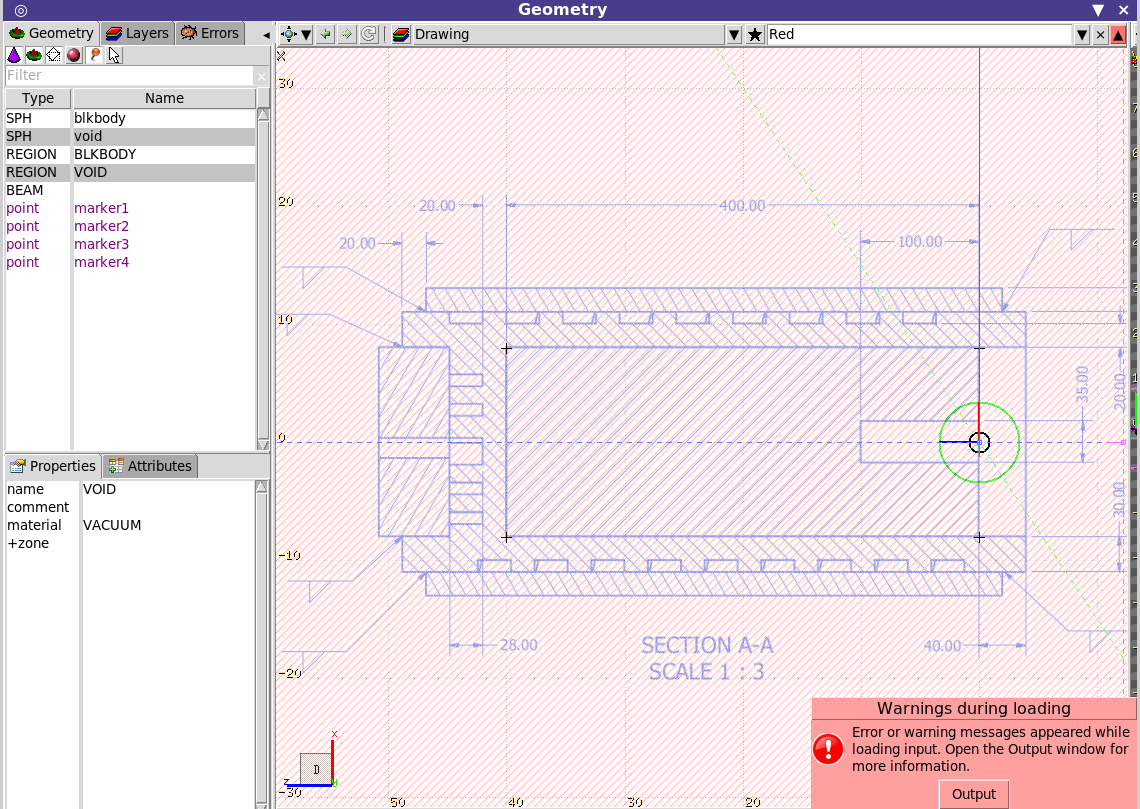
After creating the layer, the 4 markers that have been used for the
calibration are shown on the viewport (can be used as snapping points if
needed) and they are also appearing on the list-box on the right with a
Magenta color showing that the visible attribute is On.
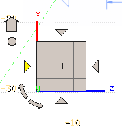
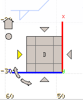
Hover to the mouse over the Orientation cube and click Twice
the Left triangle as shown in the image in Yellow.
so as to rotate the Z axis by 180 degrees.
Press Control-S key to save the project
Firstly we need to create all necessary bodies. This can be done graphically, profiting
from the snapping mechanism of flair.
The void template we used, generated two concentric spheres and defined two
REGIONs, BLKBODY and
VOID.
It is easier to visually see the undefined regions than over-defined, so as a first
step we will delete the expression of the VOIDREGION and we will re-created it at the end.
It snaps on the grid, markers, other bodies and intersection
points from bodies
Click on the
Geometry
tab above the
listboxes, and click the entry
REGION | VOID
.
The bottom listbox should populate the
Properties
of the REGIONVOID
Click to select the
zone01 | +void
Press Delete key to delete the zone01.
The viewport should look like that now.
The red titled lines show that it is undefined the
region, and the error message, complains since there is an empty expression.
Add the infinite cylinders
ZCC
centered at zero.
To add a body, any of the following steps can be used:
From the ribbon
Body
Using shortcut [b] which opens the bodies menu.
Using shortcut [B] (capital) which re-inserts the
last inserted body type.
Using [Spacebar] which opens the Insert pop-up menu
Right-click and select the body insert
When adding many bodies you can leave permanently the bodies insert menu by
first opening the menu from the menu bar or the toolbar, and then clicking
the ------ item to tear-off from the menu bar.
Add a new body
ZCC
The status bar should display “Adding body 'ZCC'”
The color of the bodies in the menu reflects the axis direction (RGB): X: Red Y: Green z: blue
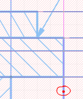
[1] Left-click on any point close to the Z=0 [2] drag the mouse upwards towards the border lines of the beam entrance
cylinder and click the mouse again
A new cylinder will be created with x=y=0 and radius close to 1.75cm. If it is
not exactly 1.75cm, then you have to zoom-in and move the cylinder boundary to
the exact location, or you can type in the radius on the left listbox
Click the name: field on the bottom-left listbox of the
Geometry
tab.
Or press the n key and it will move the focus to the listbox on the left
with the body properties.
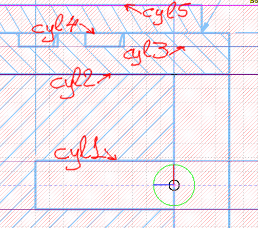
Rename the cylinder to cyl1
Press the ESCape key to unselect the current body.
Repeat the process for the remaining cylinders.
For this tutorial the cooling spiral will be omitted at the back (left-side of
the image)
To repeat the last body addition use the shortcut [B] capital
all subsequent bodies will use the same name prefix with an increasing
number as suffix
Add a Z-plane
XYP
on the right of the geometry
at Z = -4 cm
Rename this body to z1
Press B key (B-CAPITAL) to repeat
adding Z-planes
XYP
for each vertical
line you see limiting the dump, cooling pipes etc.
Since we cannot add a spiral in FLUKA we will emulate the surrounding cooling
spiral as cylinders.
Do not forget to add a plane also at the beam entrance
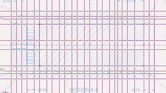
Now the image should look like the above. With 5 cylinders (or more if
you add the back ones) and 25 planes
Press Control-S key to save the project
The geometry editor of flair has an advanced feature of editing graphically the regions,
more correctly the “Zones” of the regions. Just to remind the concept,
“zone” is a portion of space that is described by the + Intersection and
- Difference operator, NO Union.
A REGION is defined as a union of zones.
Zone is a very fundamental concept in FLUKA since the particle tracking is
performed always in a single zone. While the region is used to define the
properties on a zone. Thus, the simpler the zone description is, the
faster the simulation will go!
Overlaps of zones are permitted only if they belong to the same region. Actually
zone overlaps is encouraged since it will result to simpler expression and bigger
volumes therefore faster tracking and less zone switching.
With parenthesis the concept of zone doesn't exist. FLUKA will try to expand
the parenthesis to a union of zones. It can fail when excessive parenthesis are
used. Even though flair can accept both parenthesis and/or the expanded form,
graphically the user can only edit/modify zones without parenthesis!
Zone Editing
Please note that zone editing in flair is completely different than all traditional
CAD or CAD-like 3D programs. In flair the editing is done in 2D and the user has to
ensure for the 3D outcome by controlling the other viewports. The idea behind this,
is that each body splits the space in two zones, the inner and outer one. A
selection of 2 bodies splits the space into 4 zones, and for n bodies to
2n zones, which many of them could be void. At this point
the user needs to select graphically the zone he is interested in. The procedure
(graphically) is the following:
Please refer to the flair online manual or FLUKA course slides for a more detailed
explanation on the zone editing.
Add Zone on a NEW REGION
If unsure, press the ESCape key to ensure that NOTHING is selected.
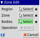
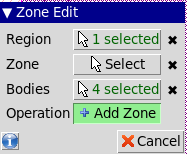
Press the
Zone
button from the ribbon. The Zone Edit dialog will appear
Short: d (small d) for define
Click on the Bodies in the dialog
and Select the bodies that define the
boundary of the zone. See flair manual slides for managing the
selections.
Since ONLY bodies are selected and nothing else,
the Operation will change to
Add Region
Click on the Operation and hover the mouse in the geometry
to select the zone you are interested
Click on the zone and flair will create a new REGION
and it will add a new Zone01 inside with the expression that
it calculated from the location you clicked.
Add Zone on an EXISTING REGION
Same procedure as before with the addition that we need to select an existing
REGION
Press the
Zone
button from the ribbon.
Click on the Region: button in the dialog
and select the region you want to ADD the zone to.
Click on the Bodies and Select the bodies that define the
boundary of the zone.
Since there is a REGION and bodies selected
the Operation will change to
Add Zone
Click on the Operation and hover the mouse in the geometry
to select the zone you are interested
Click on the zone and flair will ADD to the selected REGION
a new ZoneXX
MODIFY an existing Zone
Same procedure as before with the addition that we need to select an existing
REGION and an existing Zone##
Press the
Zone
button from the ribbon.
Click on the Region: button in the dialog
and select the REGION you want to add the zone to.
Click on the Zone button in the dialog and
select the Zone of the selected REGION you want to MODIFY.
Selecting a Zone, flair will AUTOMATICALLY select all bodies of that
zone.
Click on the Bodies in the dialog, and Select the bodies that
define the boundary of the zone
Since there is a REGION, a Zone and bodies selected
the Operation will change to
Modify Zone
Click on the Operation and hover the mouse in the geometry
to select the zone you are interested
Click on the zone and flair will MODIFY the ZONE on the selected REGION
DELETE a Zone
Select the region
Select the zone (graphically or from the properties list-box)
Press [Del] or [Backspace] and the zone will be deleted.
WARNINGeven though the region and the bodies are also selected,
they will not be deleted at this moment.
Pressing [Del] for second time all the selected bodies will be deleted
Pressing [Del] for third time the selected region will be removed.
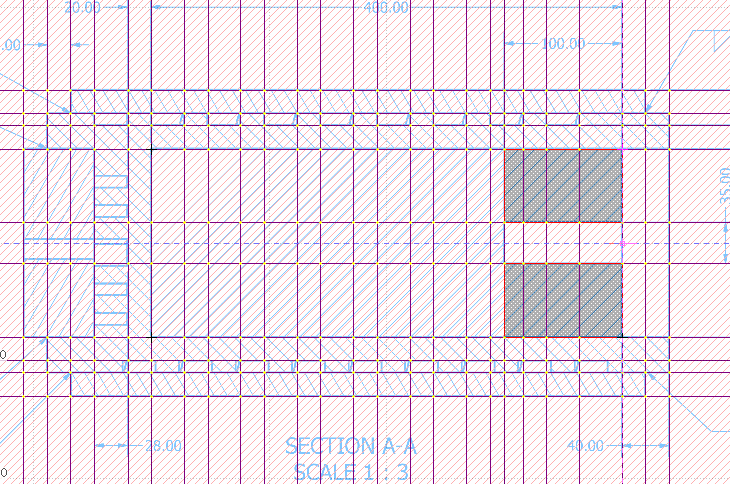
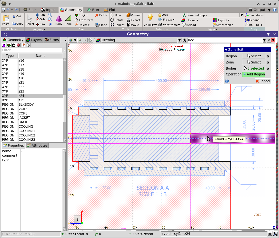
We start building the region of the “Core dump”. It should be
composed by two zones, one on the right with the entrance hole and the rest.
Hit Escape couple of times to be sure that no objects are selected.
Press the
Zone
button to open the Zone Edit dialog
Click to select the Bodies of the dialog. (if it is not already
selected)
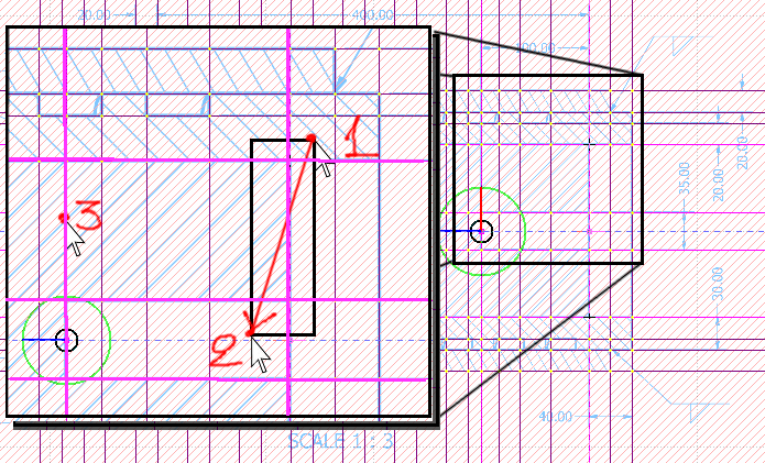
Move the mouse a bit outside of the upper-right corner of the first zone
location 1
Click at location [1] the Left-mouse button and keep pressing it.
drag the mouse to location [2] to select
the 3 bodies on the right side (two cylinders cyl1 and cyl2)
and one plane z3. (Maybe the naming is different)
The dialog should say that Bodies: 3 Selected
The selected objects will appear as
light magenta.
While the visible objects appear as
dark magenta
Click to select the plane at the entrance location [3]
On the Zone Edit dialog click the Operation button
which should say
Add Region
Moving the mouse in the viewport will highlight the possible zones with
the selected bodies. Click to select the zone as shown below
Automatically a new REGION named
REG1 will be created, with the zone expression
assigned
zone01 | +cyl2 +z24 -cyl1 -z3
,
and material assigned the last one used. Since we didn't use anything before
it will be VACUUM
Note: that the bodies names in the expression might be different in your
case.
Change the REGION name from REG1 to CORE
Click on the Material in the listbox to change it to CARBON
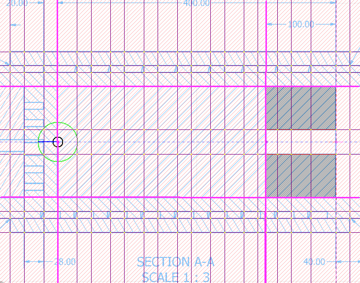
Press the
Zone
button to open the Zone Edit dialog
It should still have 1 Region and 4 Bodies selected.
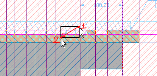
Click on the Bodies and modify the selection as follows:
Unselect the right-most plane and the inner cylinder and select the left
plane as shown below
Click on the Operation button of the dialog which should show
Add Zone
Hover the mouse of the central core of the dump and click
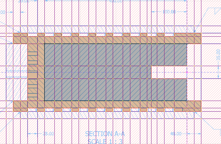
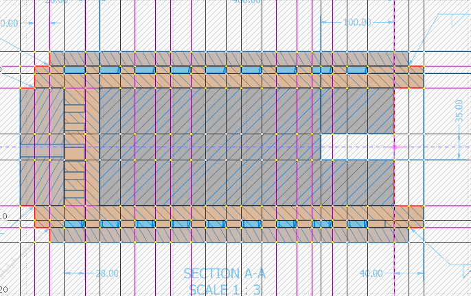
Continue the procedure to create the region JACKET with material
COPPER as shown below
In the JACKET, all the spiral pipes are modeled with cylinders.
To add the zones select the region (if not selected) and drag a small
rectangle around like below.
Repeating the same procedure create the following regions,
COVER with IRON
BACK with IRON
COOLING with WATER
until the image of the viewport looks like the following
Press the ESCape key 3-4 times to unselect everything.
The ESCape key is progressive as the selections.
If you have a REGION, Zones and Bodies selected
hitting once it will unselect the Zone, twice it will unselect
the Bodies and the third time the REGION
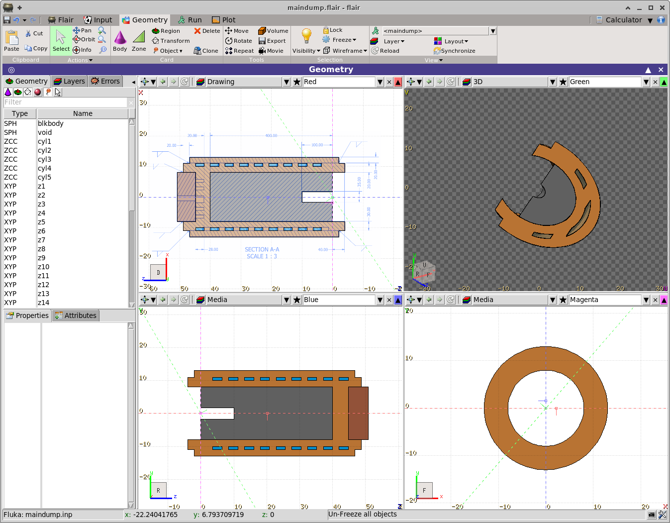
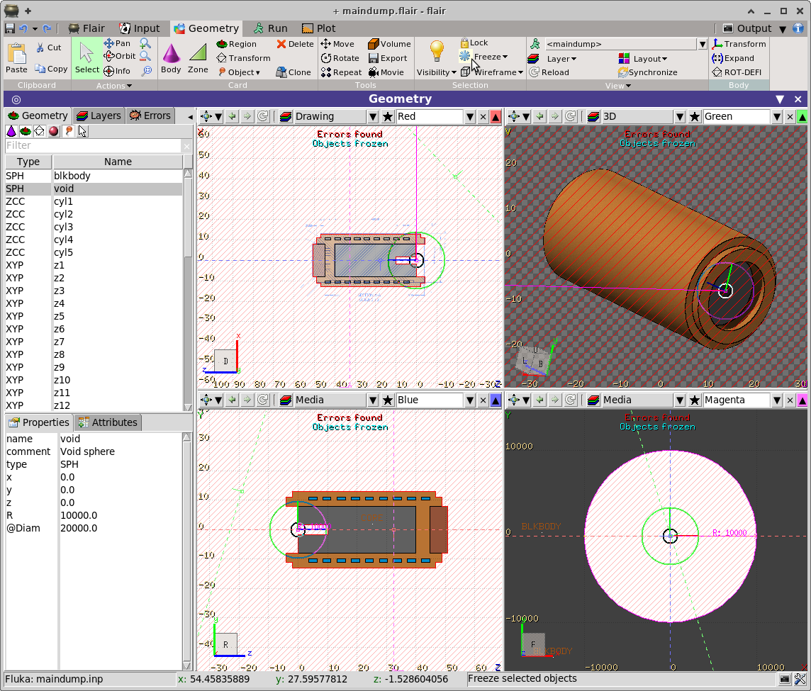
Click the
Layout ▼
to see all 4 viewports
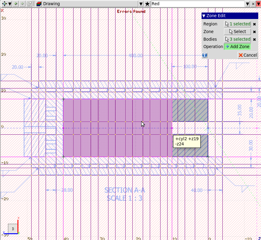
We need to correct the REGIONVOID we destroyed in the first step.
For this we don't need the visibility of the bodies.
Click on the drop down menu of the
Visibility ▼
button on the ribbon, and select the
Hide All
When editing the expression of REGIONVOID
we need to use always the Bodyvoid. The
big sphere which is visible when we zoom in.
An easy way to avoid zooming-in/out is to Freeze some bodies, so
they will appear in all expressions and we don't have to explicitly select
them every time.
Select the
SPH | void
body
from the top-left listbox and click the
Freeze ▼
icon on the tool bar.
The message objects frozen will appear.
Select the
REGION | VOID
from the top-left listbox
Click on the
Zone
button (shortcut d)
Create the zones of the surrounding VOID keeping
in mind that the SPHvoid
is *always* selected.
When you finish the message Errors found should
disappear
Finally click on the
Unfreeze All
to unfreeze the frozen bodies.
If by mistake you have created multiple regions like COOLING1, 2, 3,
or CORE 1,2.. you can select them and click the
Join
button
to create one REGION out of them
Press Control-S key to save the project
Lets make now a nice 3D plot of our dump. There is already an existing 3D layer which is
quite primitive so several options will be added on it.
Click on the
Layout ▼
to visualize all 4 viewports.
You should have an image like
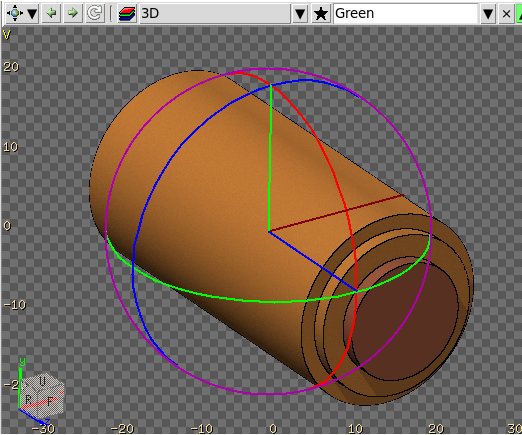
Go to the Green viewport (top-right) which should
be already in 3D. We are looking from the 45° azm and polar angle the plot
towards the center O(0,0,0).
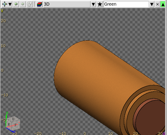
Pan backward with Control + Mouse-wheel towards you,
the viewport until you see the whole image, like:
Click with the Middle mouse button somewhere at the middle of our
displayed dump.
The middle mouse button will center the plot to this location and set it as a
pivot point for all rotations.
Click on the ribbon
Orbit
button. The orbit trackball will appear.
You can orbit at any time directly with the middle mouse button, by pressing
the Control key
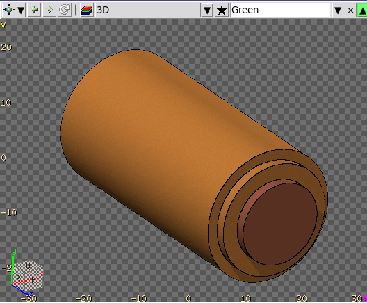
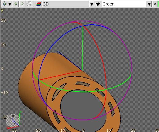
Click and drag the mouse on the Green ellipse which rotates
around the Y-axis to make a rotation of about 180°.
The same operation you can make from the Orientation cube.
Note that everything in the orientation cube even the axis are clickable and
perform an action.
Pan backward the viewport with Control + Mouse-wheel until you see all
the dump.
Press t key to remove the trackball.
Either pan the image dragging the middle mouse button or simply click it
in the middle of the dump.
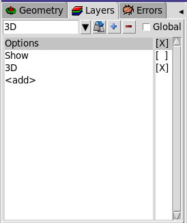
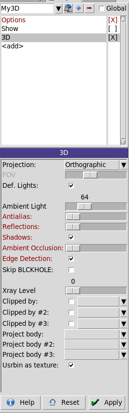
We will make now a new 3D layer to customize it a bit.
Press the button on the mini-toolbar
of the green viewport, and it will show the layers tab and activate the 3D
layer.
Press the button on the layer,
and a new layer named 3D 01 will be created based on the 3D.
Renamed it to My3D
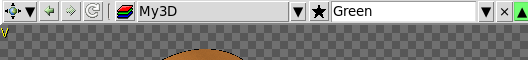
Go to the Green viewport and
select from the dropdown layers menu the new layer My3D
Again in the layers listbox select the
3D | [X]
item
and the 3D options will appear below.
Experiment with the options:
Antialias
Edge detection
Xray level
e.g. add a bit of Xray 30-40 should be ok
Go to the magenta viewport
and add an
RPP
body
as in the image.
Correct the length in the Red or Blue viewports
Name it as clip
Go back to the My3D → 3D layer options
and in the Clipped by: option select
the new clip body.
The Green viewport should
now be clipped with and should look like this
 flair
flair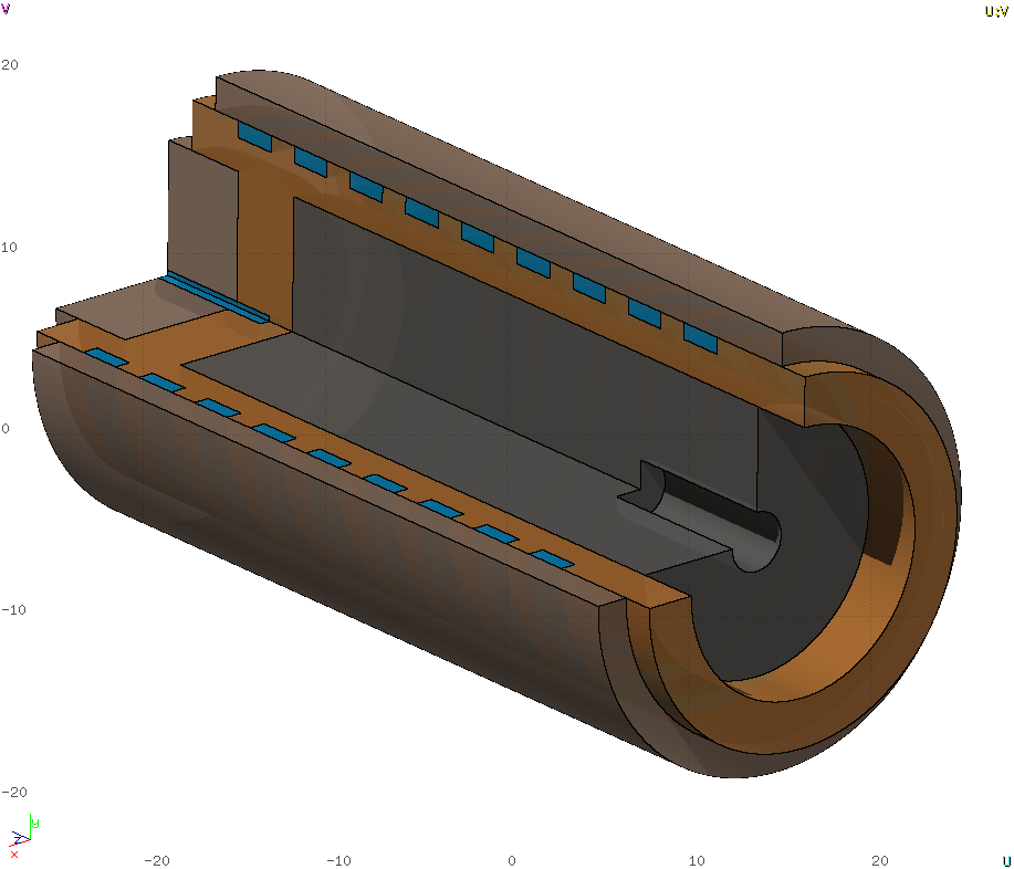

 button to load
the drawing.
button to load
the drawing.
 Markers coordinates:
 The error should be almost zero
 Note that the image is reflected due to the coordinate system we used.
 so as to rotate the Z axis by 180 degrees.
 The
The 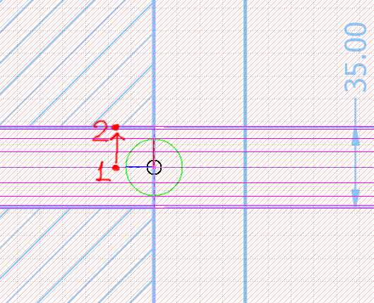 A new cylinder will be created with x=y=0 and radius close to 1.75cm. If it is
not exactly 1.75cm, then you have to zoom-in and move the cylinder boundary to
the exact location, or you can type in the radius on the left listbox
A new cylinder will be created with x=y=0 and radius close to 1.75cm. If it is
not exactly 1.75cm, then you have to zoom-in and move the cylinder boundary to
the exact location, or you can type in the radius on the left listbox
 For this tutorial the cooling spiral will be omitted at the back (left-side of
the image)
For this tutorial the cooling spiral will be omitted at the back (left-side of
the image)
 Now the image should look like the above. With 5 cylinders (or more if
you add the back ones) and 25 planes
Now the image should look like the above. With 5 cylinders (or more if
you add the back ones) and 25 planes
 Automatically a new
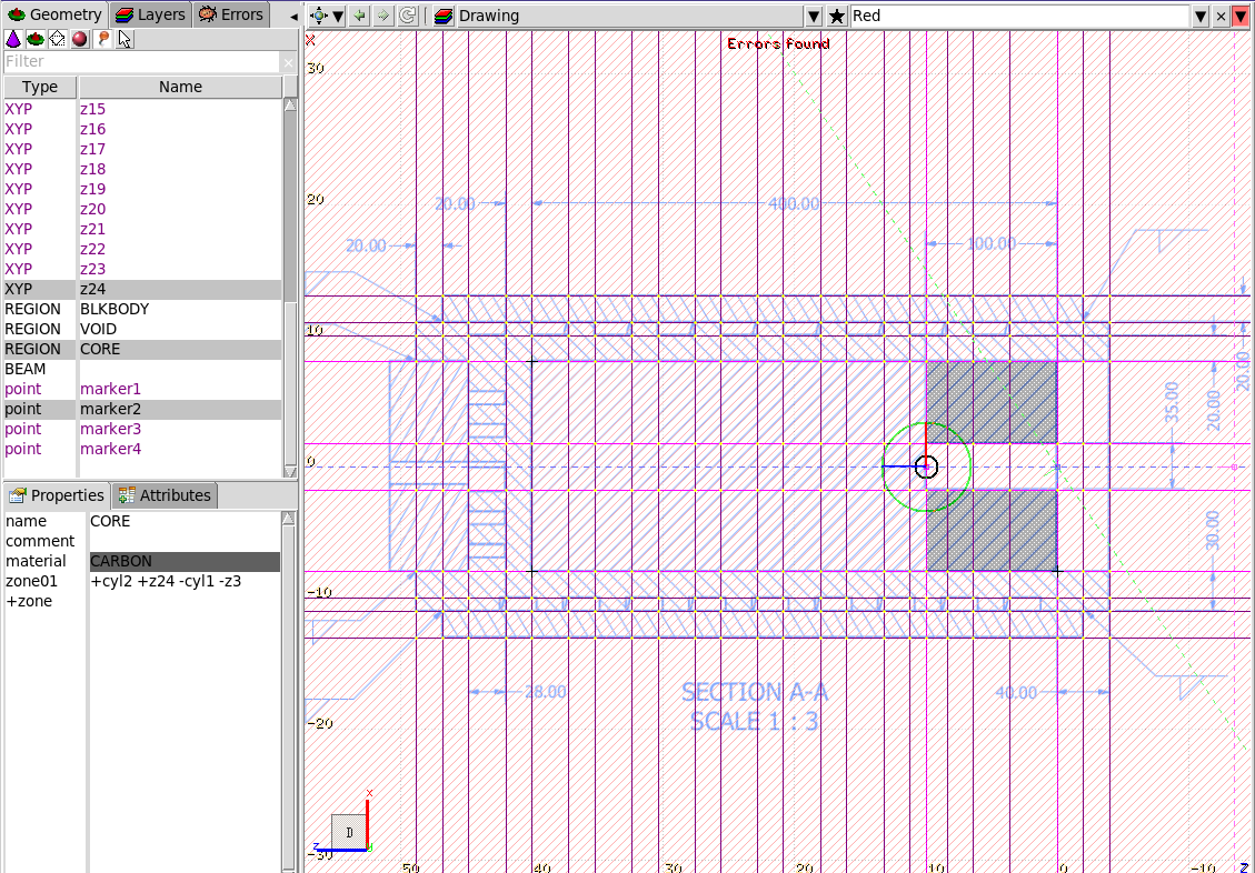
 It should still have 1 Region and 4 Bodies selected.
 When you finish the message